Cisco Packet Tracer 8.x labs
Network diagram
The aim of this lab is to test your ability to configure VLAN and VTP on a small network of 4 switches using Packet Tracer 8.2.
This lab will help you to prepare the VTP testlet and simlet questions of the Cisco CCNA exam.

Introduction
PPP is a non-proprietary WAN data-link layer encapsulation protocol which can be viewed as an enhancement of HDLC as it embeds many additional features when compared with HDLC:
- PPP Authentication. Supported authentication protocols are PAP and CHAP
- Compression
- Error detection
- Multilink to provide load-balancing over multiple network interfaces
Network diagram


Lab instructions
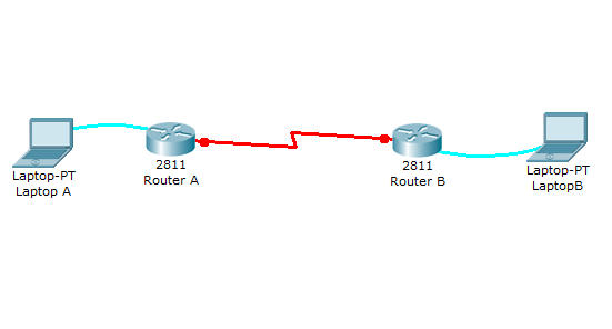
This lab will test your ability to configure PPP on a serial link in Packet Tracer 8.2. Practicing this labs will help you to better understand what is a DCE, a DTE, and aclock rates on a serial router interconnection and make you ready for the CCNA PPP labs and simlets.
1. Use the connected laptops to find the DCE and DTE routers. You can connect to the routers using CLI.
2. Configure the routers with the following parameters :
- Clock : 250000
- PPP link between the routers
- DCE IP : 192.168.10.5/30
- DTE IP : 192.168.10.6/30
3. Check IP connectivity between the two routers using the ping command.
Lab solution
1. Use the connected laptops to find the DCE and DTE routers
The show controllers <serial interface> command is used to determine which side of the cable is the DCE side.
In this example, Router-A is the DTE side, and Router-B the DCE side (DCE V.35, clock rate set).
Router-A#show controllers serial 0/0/0
Interface Serial0/0/0
Hardware is PowerQUICC MPC860
DTE V.35 TX and RX clocks detected

Router-B#show controllers serial 0/0/0
Interface Serial0/0/0
Hardware is PowerQUICC MPC860
DCE V.35, clock rate 2000000
2. Configure the routers with the following parameters
Router-B beeing the DCE, clock rate has to be configured on Router-B serial 0/0/0 interface
Router-B(config)#interface serial 0/0/0
Router-B(config-if)#clock rate 250000
Then, configure PPP encapsulation and IP address on Router-B serial 0/0/0 interface. The encapsulation ppp configures PPP protocol on the serial interface. PPP authenication can be oprtionnally configured using the following IOS commands which are not used in this lab :
- ppp authentication : Set PPP link authentication method
- ppp pap: Set PAP authentication parameters
Router-B beeing the DCE side of the serial link, the 192.168.10.5/30 IP address is configured on Router-B serial 0/0/0 interface. Don't forget to enable the interface with a no shutdown command.
Router-B(config)#interface serial 0/0/0
Router-B(config-if)#encapsulation ppp
Router-B(config-if)#ip address 192.168.10.5 255.255.255.252
Router-B(config-if)#no shutdown
The show interfaces serial 0/0/0 confirms that PPP encapsulation is enabled on the interface : Encapsulation PPP, loopback not set, keepalive set (10 sec)
Router-B#show interfaces serial 0/0/0
Serial0/0/0 is up, line protocol is up (connected)
  Hardware is HD64570
  Internet address is 192.168.10.5/30
  MTU 1500 bytes, BW 1544 Kbit, DLY 20000 usec,
     reliability 255/255, txload 1/255, rxload 1/255
  Encapsulation PPP, loopback not set, keepalive set (10 sec)
  Last input never, output never, output hang never
  [...]
Finally, configure PPP encapsulation and IP address on Router-A serial 0/0/0 interface. The link becomes up as both routers are correctly configured.
Router-A(config)#interface serial 0/0/0
Router-A(config-if)#encapsulation ppp
Router-A(config-if)#ip address 192.168.10.6 255.255.255.252
Router-A(config-if)#no shutdown

%LINK-5-CHANGED: Interface Serial0/0/0, changed state to up
3. Check IP connectivity between the two routers using the ping command.
Issue a ping from Router-A to Router-B to test network connectivity between the two routers.
Router-A#ping 192.168.10.5

Type escape sequence to abort.
Sending 5, 100-byte ICMP Echos to 192.168.10.5, timeout is 2 seconds:
!!!!!
Success rate is 100 percent (5/5), round-trip min/avg/max = 3/3/4 ms
Introduction
HDLC is a data link protocol used on synchronous serial data links. Because the standardized HDLC cannot support multiple protocols on a single link (lack of a mechanism to indicate which protocol is carried), Cisco developped a proprietary version of HDLC, called cHDLC, with a proprietary field acting as a protocol field. This field makes it possible for a single serial link to accommodate multiple network-layer protocols.
Cisco’s HDLC is a point-to-point protocol that can only be used on serial links or leased lines between two Cisco devices. PPP has to be used when communicating with non-Cisco devices. HDLC is the default encapsulation on serial links in a Cisco router. However, to change the encapsulation back to HDLC from PPP, use the following command from interface configuration mode:
Router(config-if)#encapsulation hdlcWith a back-to-back serial connection, the ISR router connected to the DCE end of the serial cable provides the clock signal for the serial link. This clock is received by the DTE device. The clock rate command in the interface configuration mode enables the router at the DCE end of the cable to provide the clock signal for the serial link. The default clock rate is 64000.
Introduction
A new switch just purchased from Cisco contains no default configuration. You need to configure the switch with setup mode or from scratch using the command line interface (CLI) before connecting it in your network environment.
As a Cisco CCNA certified professional, it is very important to know the basic Cisco switch configuration commands to improve the performances and the security of the enterprise network.
Network diagram

Download free Cisco Packet Tracer 8.2.2 labs designed by our team for CCNA and CCNP Enterprise training.
Packet Tracer 8.2.2 is compatible with labs created in previous Packet Tracer versions 8.1, 8.0, 7.x. However, the files created in Packet Tracer 8.2.2 are not backward compatible with previous versions. Please Download Cisco Packet Tracer 8.2.2 on Cisco Netacad before using our labs.
All activities included in the new CCNA v7.02 curricula are fully compatible with Packet Tracer 8.x software updates. CCNA v7 students should continue to use Packet Tracer 7.2.2. It is highly recommended for CCNA Routing & Switching (v6), CCNA Discovery, CCNA Exploration, CCNA Security students to stay with Packet Tracer 7.2.2 as they could encounter a warning messages in Packet Tracer 8.2.2